Cyber Security through Operational Technology (OT)
Fast charging for electric vehicles
Electric driving without restrictions – that is the goal when buying an electric vehicle. Guaranteed mobility and flexibility thanks to DC fast charging and its unwanted dependence on the charging system and charging station equipment.
But what does fast charging mean and how safe is it for the user?
Charging with direct current (DC) always requires a connection between the EV and the charging point via a permanently connected charging cable. Wired charging of electric vehicles (EV), also known as conductive charging, can be carried out in different charging modes, which are defined in the system standard DIN EN 61851-1 (VDE 0122-1). Charging mode 4 is defined for charging with direct current (DC charging) at permanently installed charging stations. This special DC charging infrastructure offers a high level of electrical safety and protection of the installation against overloading, e.g. fire protection. Further protection against contact and manipulation is provided by locking the charging plug connection during the charging process. A special communication interface is used to communicate and control the charging process. The interface between the vehicle and the charging point is a decisive criterion for safe and convenient use of the charging infrastructure.
Different standards for fast charging
To date, there are many different and mutually incompatible charging plugs and coupling variants on the market. Five standards have become established worldwide for fast charging.
- CCS (Combo 2) – Combined Charging System preferably in Europe and the USA
- CCS (Combo 1) – Combined Charging System single-phase preferably in the USA
- CHAdeMO – “CHArge DE MOve” standard preferably in Japan
- Tesla Supercharger
- GB/T standard preferably in China
In Germany, there are mainly 3 DC fast charging systems. CCS (Combo 2), CHAdeMo and Tesla Supercharger.
CCS (Combo 2)
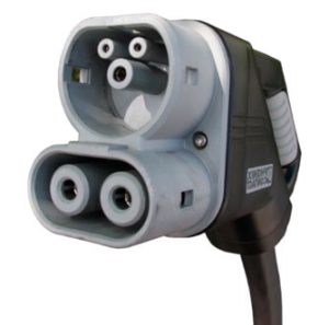
The Combined Charging System (CCS) is an open, universal charging system for EVs based on the international standards IEC 61851-1, IEC 61851-23, Annex CC and IEC 61851-24 for the charging equipment.
The standards for charging connectors are defined according to IEC 62196 (EE and -EF configuration only). The vehicle-side CCS connection combines three-phase AC charging with the option of fast DC charging.
As a system, CCS includes the connectors as well as the control functions and communication between the EV and the infrastructure.
The extended communication provided for DC charging with CCS is based on DIN SPEC 70121 and ISO 15118. On the vehicle side, electrical safety is specified by ISO 17409.
CHAdeMO
CHAdeMO is a plug-in system developed in Japan for charging electric cars and plug-in hybrids. “CHAdeMO” is an abbreviation for “CHArge de MOve,” equivalent to “charge for motion,” and is a play on words for “O cha demo ikaga desuka.” in Japanese, which means “Let’s have a cup of tea while charging.”
The CHAdeMO plug established itself as the first standard for charging electric vehicles with direct current (DC). Car brands that have the plug on board as standard are Toyota, Kia, Mitsubishi and Nissan. Tesla offers an adapter for connecting to a CHAdeMO charging station for several models.
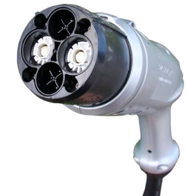
Functional testing and measurement of charging systems
The charging device is a stationary electrical system that can be operated by laypersons and should be tested in accordance with standards at publicly accessible and commercially used locations. (Initial test) The test for functionality and electrical safety is carried out by a qualified electrician. The person to be tested should have basic knowledge of assessing the measured values and testing DC fast charging systems.
The contents of the tests and the test intervals can be found in the standards, including DIN EN 61851-1/22/23/24 (VDE 0122-1/2-2/2-3/2-4), ISO 15118-1, DIN SPEC 70121, IEC 60364-6 / DIN VDE 0100-600, EN 50110-1 / DIN VDE 0105-100, manufacturer and installer instructions and, depending on the installation location and type of use, also from legal requirements.
Further information can be found in the Occupational Health and Safety Act, the Ordinance on Industrial Safety and Health, ZVEH guidelines and the accident prevention regulations of the employers’ liability insurance associations.
Why is it being checked?
According to Article 2 (2) of the German Basic Law, everyone has the right to life and physical integrity. During the charging process, the user comes into direct contact with the charging station technology. Safety requirements must therefore be met under normal conditions (including various climatic conditions), with particular consideration given to foreseeable misuse and abuse, accidents and vandalism.
The test to be carried out determines the current actual condition and compares or evaluates this with the target condition. In the event of deviations outside the specified tolerance limits, the system is repaired and tested again.
In addition to the legislation, the interest of the client, there is now a great deal of business interest on the part of the inspector, because according to the BNetzA, 6,493 fast charging points have been officially registered in Germany as of 01.07 2021 in addition to the 38,876 normal charging points.
The right choice of measuring / testing devices
During testing, the focus is on the safety of the person carrying out the test, the electrician. Therefore, the correct selection of a suitable measuring/testing device is particularly important. These must comply with the relevant manufacturer and device standards. In particular, the individual test procedures should comply with the standards. The relevant standard is DIN EN 61557 (VDE 0413) Electrical safety in low-voltage distribution systems up to 1,000 V AC and 1,500 V DC – Equipment for testing, measuring or monitoring protective measures. The correct measurement category is also very important. This specifies the permissible areas of application of measuring and testing devices for electrical equipment and systems for use in low-voltage networks. The classification of the measurement category is defined by IEC 61010-1 (Safety requirements for electrical equipment for measurement, control and laboratory use).
Testing DC charging points with the PROFiTEST H+E XTRA C
The standard-compliant testing of DC charging points includes all measures to check that the electrical system and communication comply with the requirements.
The test includes inspection, testing and measurement as well as the preparation of a test report.
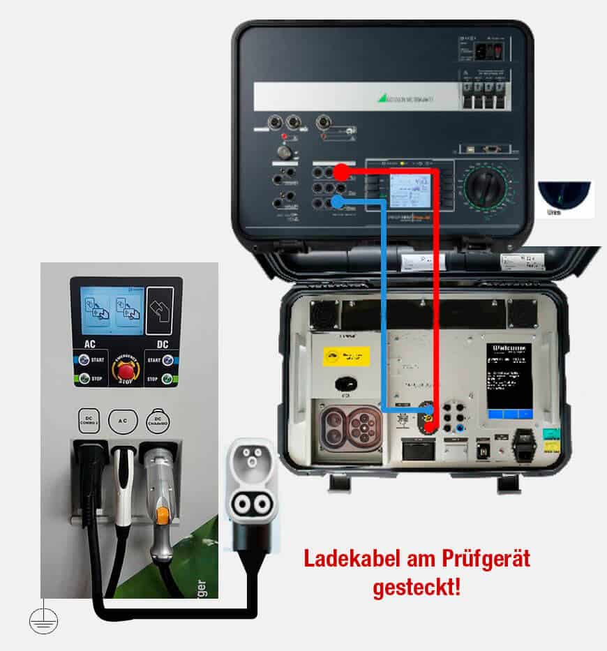
Visit
Before the functional check, including the communication, the DC fast charging station is inspected according to defined specifications. Please note that this is a stationary electrical system that can be operated by laypersons! The visual inspection must be documented and can also be supplemented with corresponding images.
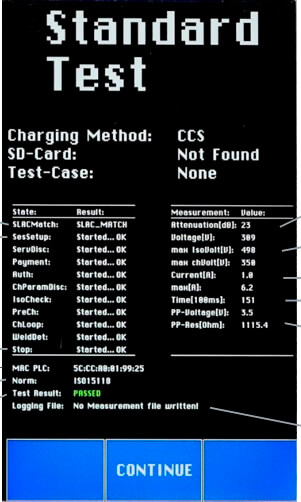
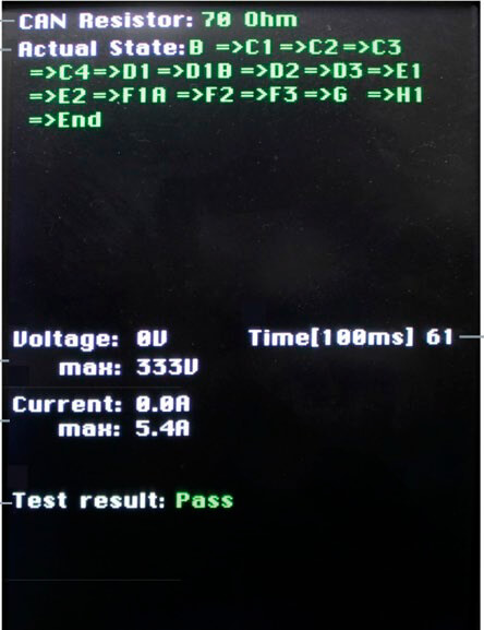
Functional testing of DC-CCS communication (in accordance with ISO 15118-1 / DIN SPEC 70121)
To check the communication, it is important that all necessary safety instructions are observed. The PROFiTEST H+E XTRA C diagnostic device must be connected to the DC charging point and the corresponding standard / standard sequence ISO 15118-1 or DIN SPEC 70121 must be preselected. After the start, authentication is carried out via telephone hotline, cash payment, cash card, debit card, RFID card, NFC device, cell phone text message, smartphone app, Internet, Plug & Charge, etc. The diagnostic tester simulates an EV with DC load and DC source. During the test, the subsequent steps of the test procedure and information about them are displayed.
If the result is OK, the following statements can be made:
- The load had more than 3 A during the ChargeLoop (charging process)
- The charging station is working, the EV can generally be supplied with power
- Communication normative according to ISO 15118-1 / DIN SPEC 70121 in order
Functional check of CHAdeMo communication
During the test, the subsequent steps of the test procedure and information about them are displayed. When checking the communication, it is also important here that all necessary safety instructions are observed. The PROFiTEST H+E XTRA C diagnostic device must be connected to the CHAdeMO DC charging point. After starting, authentication is carried out via telephone hotline, cash payment, cash card, debit card, RFID card, NFC device, cell phone text message, smartphone app, Internet, Plug & Charge, etc. The diagnostic tester simulates an EV with DC load and DC source.
The following test sequence is started:
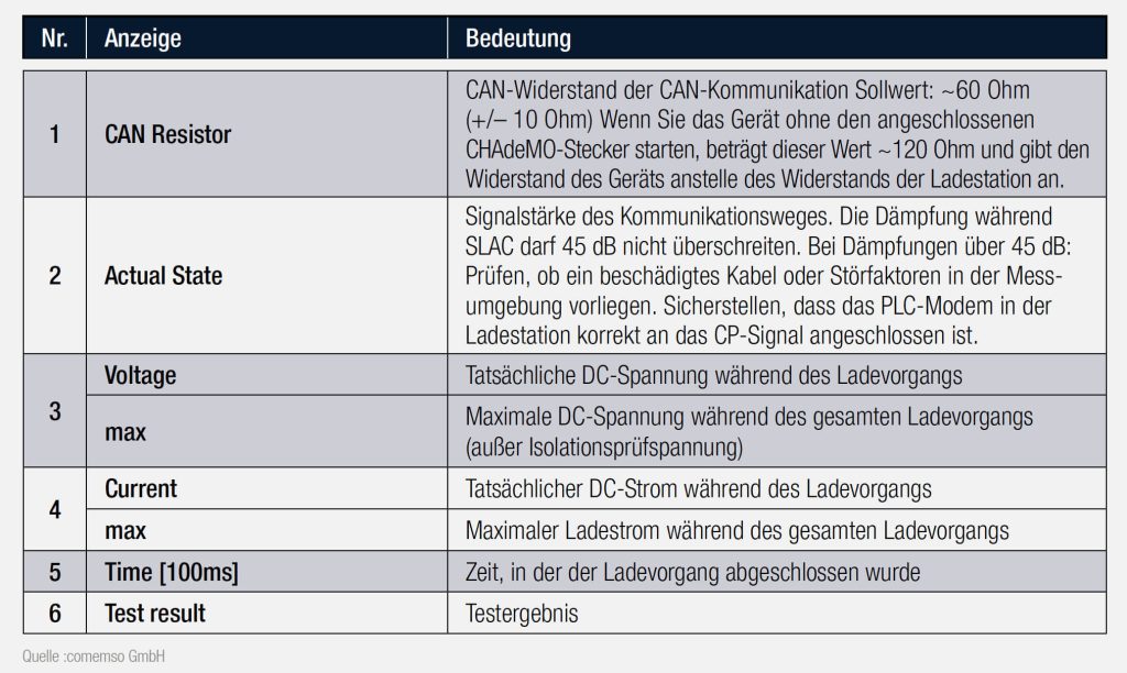
- The DC load was more than 3 A in state E2 (charging process)
- The charging station is working and the EV can generally be supplied with power
- Communication according to version 9.1, 1.0.0, 1.0.1, 1.1 in order
Standard-compliant testing of electrical safety at the DC charging point
The electrical safety test is carried out with PROFITEST H+E XTRA or PROFITEST H+E XTRA C in combination with the PROFITEST PRIME. The tests must be carried out by a qualified electrician using standard-compliant measuring instruments.
- Measurement of low-impedance continuity of the protective conductor
- Measurement of the loop resistance between DC+ and DC-
- Checking the insulation monitoring in the CCS system
- Measurement of the insulation resistance
- Measurement of residual voltage
- Measurement of touch current
- Testing the residual current device
The special feature of testing DC charging points is that most measurements and tests only have to be carried out with the load and source connected! (e.g. loop measurement)
The following standards from the field of electrical installation and protection against electric shock are
among other things:
- DIN EN 61140 (VDE 0140-1; 2016-11, Protection against electric shock – Common requirements for systems and equipment)
- DIN IEC/TS 60479-1 (VDE 0140-479-1; 2007-05, Effects of electric current on humans and domestic animals – Part 1: General aspects)
- IEC 60364-5-54 (DIN VDE 0100-540; 2012-06, Erection of low-voltage installations – Part 5-54: Selection and erection of electrical equipment – Earthing systems and protective conductors)
- IEC 60364-4-41 (DIN VDE 0100-410; 2018-10, Erection of low-voltage installations – Part 4-41: Protective measures – Protection against electric shock)
- IEC 60364-5-53 (DIN VDE 0100-530; 2018-06, Erection of low-voltage installations – Part 5-53: Selection and erection of electrical equipment – Switchgear and controlgear)
- IEC 60364-7-722 (DIN VDE 0100-722; 2019-06, Low-voltage installations – Part 7-722: Requirements for premises, rooms and special installations – Power supply for electric vehicles)
- IEC 60364-6 (DIN VDE 0100-600; 2017-06, Low-voltage installations – Part 6: Tests)
- EN 50110 (DIN VDE 0105-100; 2015-10, Operation of electrical installations – Part 100: General requirements)
- IEC 60364-6 (DIN VDE 0105-100/A1; 2017-06, Operation of electrical installations – Part 100: General requirements; Amendment A1: Periodic inspections)
Measurement of low-resistance continuity of the protective conductor in the CCS system with 200 mA
According to IEC 60364-6/DIN VDE 0100-600, the continuity of protective conductors, including the protective equipotential bonding conductors via the main earthing busbar and the conductors of the additional protective equipotential bonding, as well as of active conductors in ring-shaped final circuits must be tested.
Measuring principle – the continuity of conductors is determined by a constant test current and the voltage drop at the test object.
The measurement is carried out between the PE of the plug-in system of the DC charging point and the protective conductor in the upstream electrical system.
Worth knowing
- If the test voltage is a DC voltage, the measurement must be carried out with polarity reversal in accordance with DIN EN 61557-4. The measurement must therefore be carried out with (automatic) polarity reversal of the measuring voltage or with current flow in one direction (+ pole to PE) and in the other (- pole to PE).
- Resistors that only reach a stable value after a “transient process” should not be measured with automatic polarity reversal, but with positive and negative polarity in succession.
- Resistors whose values can change during a measurement are, for example
- Resistors of incandescent lamps whose values change due to the heating caused by the measuring current
- Resistors with a high inductive component
- Contact resistances at contact points
- Mains chokes
Determination of the limit value
The calculation of the limit value is determined from the line resistance and the contact resistance. (see DIN VDE 0100 – 600: 2017-06, Appendix A, Table A1)
Measurement of the low-resistance continuity of the protective conductor in the CCS system with 25 A
Due to the high test current used, this type of measurement is particularly suitable for precise continuity tests of particularly low-resistance PE conductor systems, i.e. with large cross-sections and/or short cable lengths. In this case, the continuity of PE conductor systems is determined by injecting a mains frequency test current and measuring the resulting voltage drop.
Here too, the test is carried out at the Combo 2 connector system (PE measurement input on the PROFiTEST H+E XTRA C) and at a PE measuring point of the charging or transformer station.
Worth knowing
Due to the high test current, this can lead to undesirable heating or damage in the case of small cross-sections.

Used to check the effectiveness of protective measures for charging points
Protection against electric shock must be ensured for electrical installations. In DC installations, specific requirements in accordance with DIN VDE 0100 must also be met, as there is an increased risk of fire due to insulation faults that can cause a non-extinguishing arc.
The assessment of the effectiveness of protection against electric shock and in the event of overcurrent due to automatic disconnection at AC/DC charging points can be verified using the PROFITEST H+E XTRA or PROFITEST H+E XTRA C devices in combination with the PROFITEST PRIME device.
In this case, the actual measurement is carried out with the PROFITEST PRIME test device. The PROFITEST H+E XTRA or PROFITEST H+E XTRA C devices act as adapters in this case.
Measurement of the DC loop resistance
Due to the fact that even low contact resistances can be very dangerous, this measurement should be carried out with the PROFiTEST PRIME as recommended.
With currents of up to 400 amperes, even low contact resistances on the plug cause high heat losses. A resistance of just 0.15 milliohms is enough to turn the plug into a 25-watt soldering iron.
However, the existing compact plastic plug of type CCS 2 (Combinded Charge System) is to be retained. It is difficult for heat to escape. As the plugs are open systems and the contact surfaces can be soiled or damaged by dust or other environmental influences, even higher contact resistances could quickly cause the plugs to burn out. With potentially fatal consequences. (Source: Matthias Kübel, VW)
DC measuring method
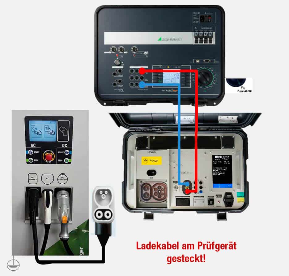
The PROFITEST PRIME enables the measurement of the loop impedance DC+ – DC-, DC+ – PE, DC- – PE, depending on the type of contacting. The loop impedance Z is measured and the short-circuit current IK is determined in order to check whether the switch-off conditions of the protective devices are met. In the case of the DC charging point, the measurement is only relevant for determining the loop impedance and the contact resistances of the connector system.
Worth knowing
The loop impedance should be measured at the furthest point of each circuit in order to determine the maximum loop impedance of the system.
Checking the insulation monitoring in the CCS system
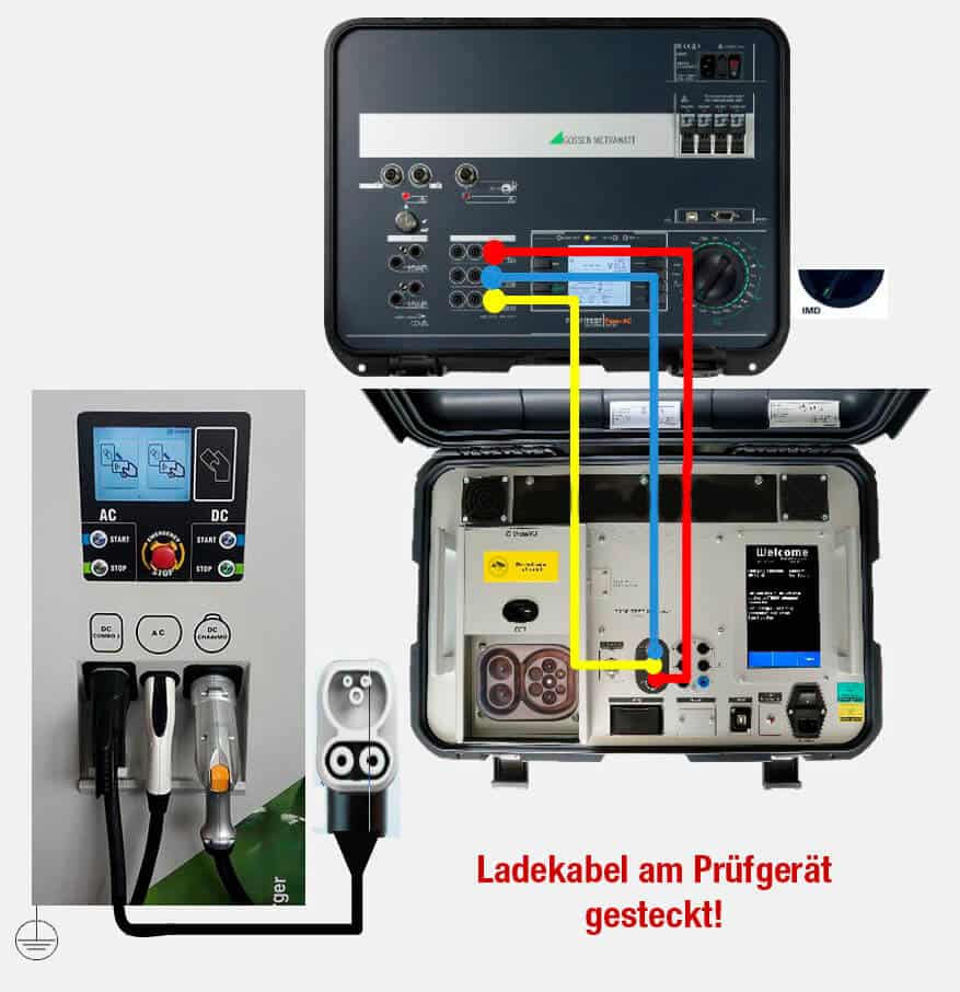
Insulation monitoring is checked by simulating defined insulation resistances and is a safety test of the EVSE to check the detection of insulation faults. This test is only carried out with DC CCS.
The PROFiTEST XTRA C simulates an EV with DC load and DC source. The charging process stops automatically after a few seconds. The tested ISO value is displayed on the screen of the diagnostic device.
Note! During the test procedure, the charging gun is automatically locked and cannot be pulled out.
Technical characteristics:
HDC+: High insulation resistance value between DC+ and PE 475 kΩ
LDC+: Low insulation resistance value between DC+ and PE 95 kΩ
HDC-: High insulation resistance value between DC- and PE 475 kΩ
LDC-: Low insulation resistance value between DC- and PE 95 kΩ
Residual voltage measurement
Measuring the residual voltage is recommended to ensure that there is no danger when touching dangerous active parts. This applies in particular to vehicle couplings if the voltage between any contacts exceeds 60 V DC or 30 V AC (effective value) during charging.
After disconnecting the vehicle coupling from the vehicle plug, 2 requirements should be met, provided that the contacts of the vehicle coupling do not fulfill the IPXXB according to IEC 60529:
- The charge between all contacts must be below 50 μC within 1 s, i.e. the voltage must not exceed 60 V DC and 30 V AC (effective value) within 1 s of disconnection.
- The energy between all contacts must be less than 0.2 J within 10 s, i.e. the voltage must not exceed 60 V DC and 30 V AC (effective value) within 10 s of disconnection.
With the PROFiTEST PRIME, the test for the absence of voltage is carried out by means of a voltage measurement in which the discharge time tu is measured.
Testing the residual current device
In accordance with the relevant standards, DC charging stations should have special protective measures. DC charging points for electric vehicles with a fixed charging cable should be equipped with an RCD residual current device on the cable or in the power supply unit. Further information on protective measures against residual currents in fixed installations can be found in IEC 60364-7-722. Compatibility with an upstream type A residual current device RCD can also be achieved by double or reinforced insulation of the circuit that causes a leakage DC current to another circuit and protective conductor or by using special sensors to detect 6 mA DC residual currents.
Worth knowing
- Residual current devices (RCDs) are used for protection by automatically switching off the power supply in the event of indirect contact. The effectiveness of this measure must be checked by inspection and measurement. Proof must be provided that disconnection occurs at the latest when the rated residual current I∆N is reached and the agreed limit value of the permissible touch voltage is not exceeded.
- The PROFiTEST PRIME offers the option of testing AC, pulse and DC-sensitive residual current devices with instantaneous (general type), short-time delayed (type G) or time-delayed tripping (type S).
Special PROFiTEST PRIME measuring method
To determine the touch voltage U∆N occurring at the rated residual current, the test device measures with a current that is only approx. 1/3 of the rated residual current. This prevents the residual current device RCD from tripping. The particular advantage of this measuring method is that you can quickly and easily measure the touch voltage at any socket outlet without triggering the RCD residual current device. The otherwise usual and cumbersome measuring method of testing the effectiveness of a point and proving that all other parts of the system to be protected are reliably connected to this measuring point via the PE conductor with a low resistance can be dispensed with.
New – Testing of 6 mA residual current devices RDC-DD / RCMB
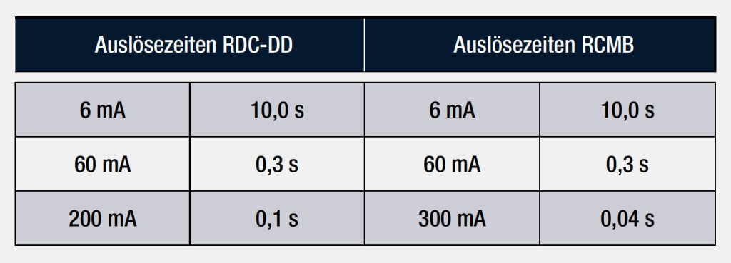
DIN VDE 0100-722 (installation regulations for charging facilities for electric mobility) stipulates that each socket for charging an electric vehicle must be protected with a separate RCD residual current device. Furthermore, additional protection is prescribed for multiphase charging of smooth DC residual currents. This can be implemented with either a type B RCD, an RDC-DD (Residual Direct Current – Detecting Device) or an RCMB (Residual Current Monitoring Module). RDC-DDs are tested in accordance with IEC 62955 and RCMBs in accordance with IEC 62752. The required tripping times are listed below:
Measurement of the insulation resistance
To avoid danger and damage caused by fault and leakage currents that can occur due to faulty cable insulation, the insulation resistance between the active conductors and the protective conductor connected to earth must be checked.
The insulation resistance is measured by applying a constant DC voltage and a test current of at least 1 mA in accordance with DIN EN 61557-2.
The test is carried out on DC charging stations without an insulation monitoring system.
If the DC charging station for electric vehicles has several DC outputs that are intended for simultaneous operation, each output circuit must also be separated from all other output circuits by basic insulation, double insulation or reinforced insulation. An additional measurement of the insulation resistance between the DC charging points is recommended here.
Worth knowing
- Insulation resistances may only be measured on de-energized objects
- Do not touch the measuring tips during the measurement. There is a risk of injury!
- Capacitive test objects are not discharged correctly during this measurement. The connection between the test device and the test object must therefore only be disconnected when the current test probe voltage is “< 10 V”.
- Before the insulation measurement, check that the device displays < 1 kΩ by short-circuiting the test leads at the test probes. This can prevent an incorrect connection or detect an interruption in the test leads.
Touch current measurement
The touch current is measured during the charging operation of an electric car at a DC charging station under certain conditions. The effective value of the touch current is 3.5 mA. If this is exceeded, requirements in accordance with DIN EN 61851-23 for a DC charging station for electric vehicles of protection class I must be met.
Worth knowing
- The part to be measured must be de-energized! If in doubt, check that there is no voltage before starting the measurement.
- Before testing, circuit parts that are connected by a fixed resistor or reference to the protective conductor (e.g. checking the connection of the EV) should be disconnected.
Summary
Legal regulations are increasing the pressure on car manufacturers worldwide to reduce the carbon dioxide emissions of their vehicles. As a result, the demand for charging options and their various charging concepts is also growing. However, the lack of infrastructure means that many users feel compelled to charge their vehicles at home for the time being. For longer journeys, however, they expect the charging process to be as fast as possible.
Due to these requirements, the DC charging infrastructure will be further expanded and must therefore be reviewed.
The inspection of fast-charging stations, i.e. DC charging points, is a constant challenge for experienced electricians. With basic knowledge of the communication of the different charging systems as well as basic knowledge of measurement methods and their application, it is possible to carry out and assess the test.
Autor
Michael Roick
Leitung Produtmanagement
Gossen Metrawatt GmbH
Tel: + 49 911 8602-787
Fax: + 49 911 8602-80787
E-mail: michael.roick@gossenmetrawatt.com

