28 Nov

Transparency in the Smart Grid

Provision of high-quality & basic measurement data with maximum flexible connectivity

The most important thing in advance: the definition of a smart grid

In order to generate transparency in the smart grid, it is necessary to provide high-quality & basic measurement data with maximum flexible connectivity. For this, however, it is important to define the smart grid semantically correctly in advance. This is essential to avoid misunderstandings between the operator and the suppliers of measurement technology and software during the project definition.

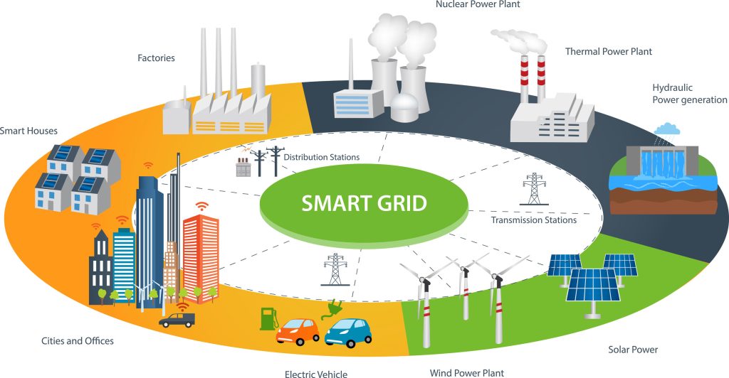
For this reason, Camille Bauer and her partner network build on the basic definition of a smart grid as described, for example, by the Swiss Federal Office of Energy:

“A smart grid is an electrical system that intelligently ensures the exchange of electrical energy from various sources with consumers of different demand characteristics by incorporating measurement and mostly digital information and communication technologies. Such a system should take into account the needs of all market players and society. The use and operation of the system can thus be optimized and made more efficient, the costs and environmental impact can be minimized, and the quality and security of supply can be guaranteed to a sufficiently high degree.”

Transparency in the smart grid

A scalable and time-synchronized measurement system covers everything

Traditionally, one measuring device for load flow measurement with current transformer or Rogowski coil is installed per 3P (L1-L2-L3) or 3PN (L1-L2-L3-N). In the case of transparency in the smart grid, for a system with 8 loads (feeders), this would mean that 8 measuring devices would also have to be used. The installation effort (e.g. 8 x 4 measuring inputs for voltage & current, 8 x supply voltage, 8 x costs for a measuring device & accessories, 8 x installation, etc.) as well as the often unavailable installation space is a problem.

Last but not least, the IT infrastructure is also burdened, since either complete Modbus RS485 networks have to be set up or many new IP addresses have to be managed in the patch. Not to forget the high effort for individual cyber protection, connectivity and general device administration. In addition, it must be ensured that all measuring devices used measure time-synchronized on all channels. And if you now want to put the power quality, e.g., according to EN50160 and an additional event monitor, into context as well, the costs and the effort then explode completely.

Transparenz im Smart Grid

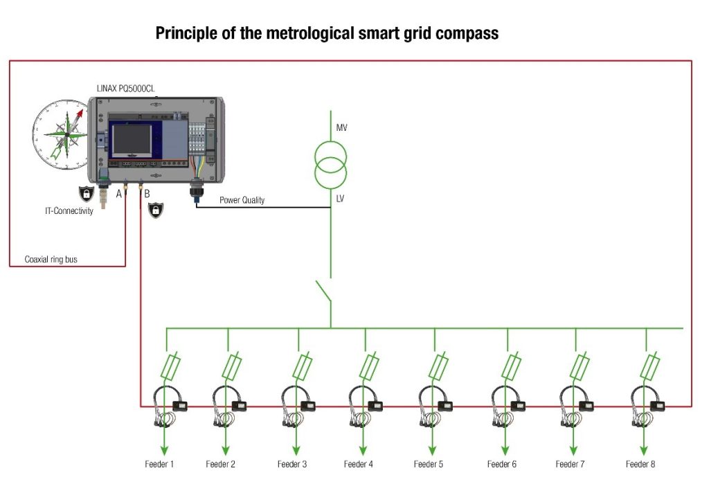
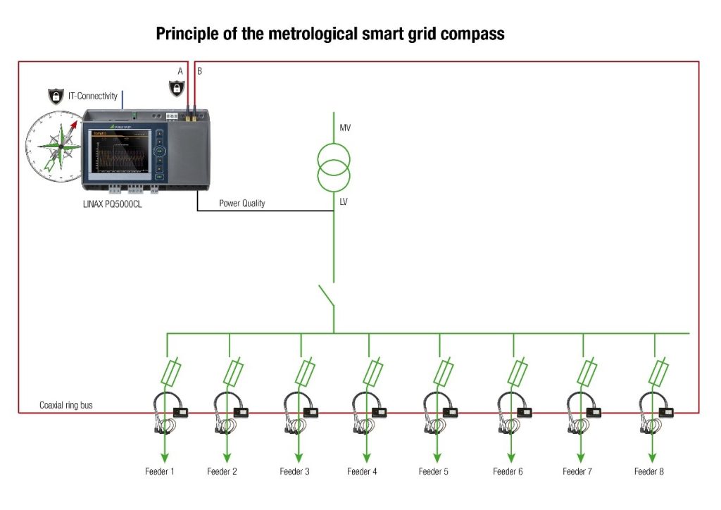
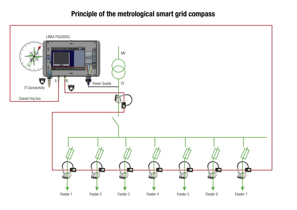
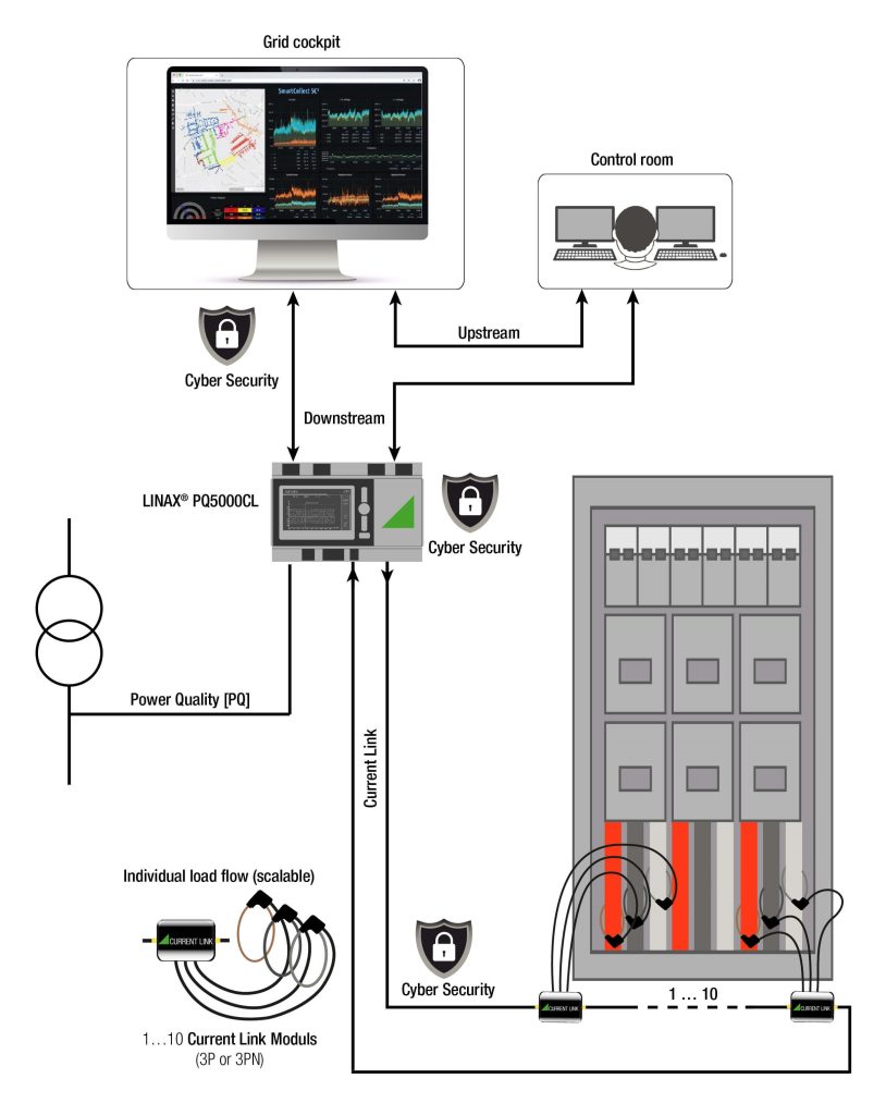
In the LINAX PQ5000CL system, everything has been integrated into one system. This is a scalable current measurement via the Current Link Module, in combination with the metrologically certified power quality monitoring of class A in the base unit. A metrological compass, so to speak. In an expansion step, the individual current channels of the Current Link Modules will still be time-synchronized in relation to the voltage events. This means that each voltage event can be viewed and analyzed with the currents/channel (planned in 2023). Thereby, the IT infrastructure is only minimally burdened, since only one participant as data concentrator takes over the consolidation and communication of all measurement data. And not to forget, the unique cyber protection on device level, which contributes significantly to the overall cyber security in the network operation.

Gapless measurement (Zero Blind)

Due to the high sampling rate (18kHz (U) / 54kHz (I)), virtually nothing remains hidden and even quick fluctuations are recorded without gaps at any time. This is important in order to provide automation (e.g. digital grid management) with high-performance, but also real data, or to create unique transparency in the smart grid (e.g. real-time digital twin). Here, the transfer of the measurement data to the base unit takes place via the coaxial ring bus system, and from there the consolidated measurement data is transferred to the parallel or higher-level system.

Current Link

Automatic range switching up to 20'000A

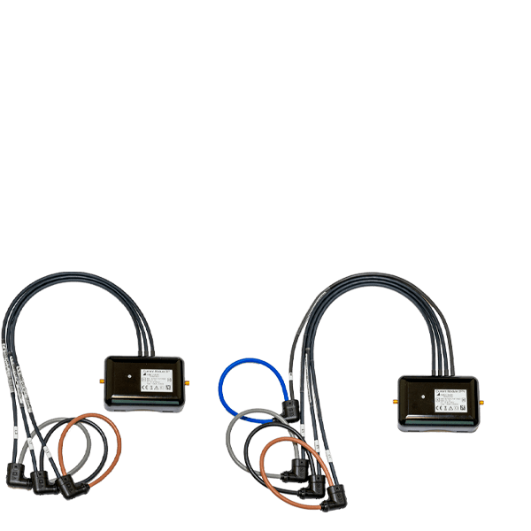
Each Current Link module (3P or 3PN) has the possibility to be used individually in a typical rated current range according to the “Factor20 technology”. Thereby, rated currents are automatically categorized by the Current Link modules into the ranges “IN1 (typical/maximum) of 400A/1’000A” and “IN2 (typical/maximum) of 8’000A/20’000A”. This means that each module can be operated permanently up to a maximum of 20’000A. This is helped by an automated range switching feature integrated in the Current Link modules. This type of functionality is optimally suited for operating a Current Link system on a variety of unequal or even symmetrically loaded rated currents and actual loads.

Example without basic current measurement (primarily for EN5160 compliance)

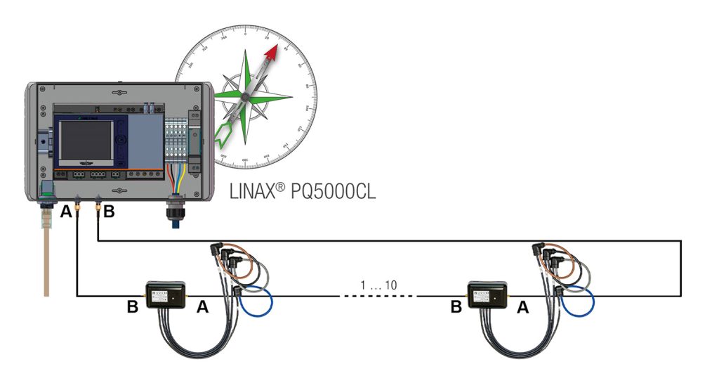
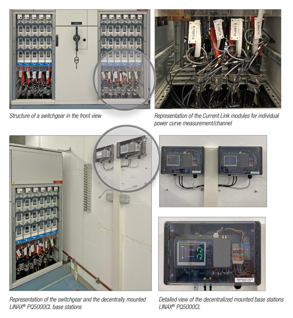
Variant 1: In field housing for wall mounting (power supply Current-Link modules included)

Variante 1

Variant 2: Top-hat rail mounting (power supply Current Link modules exclusively)

Varianten 2

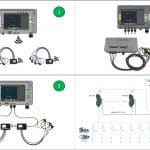
Example with base current measurement via Current Link Module

Beispiel mit Basisstrom-Messung über Current Link Modul

Signal concept proven billions of times over: coaxial lines

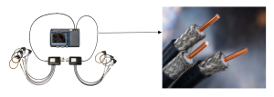
Coaxial cables are two-pole cables with a concentric structure. They consist of an inner conductor (also called core), which is surrounded at a constant distance by a hollow cylindrical outer conductor. The outer conductor shields the inner conductor from interference radiation. Coaxial cables are suitable for transmitting high-frequency, broadband signals in the frequency range from a few kHz to a few GHz.

Due to their physical properties and simple nature, coaxial cables are very well suited for scalable current link technology. The high-frequency signals are transmitted cleanly and efficiently. In addition, interference from outside as well as interference to the outside is very well shielded. The coaxial technology also makes it possible to set up ring lines with a maximum total length of 20m as a “quasi-bus”, which in turn enormously reduces the wiring effort. Thus, the auxiliary power supply of the Current Link modules as well as the signals are transmitted in one cable. This eliminates the need to feed many confusing individual cables into a distribution cabinet. At the same time, no additional load is placed on the existing IT infrastructure. Unauthorized access (e.g. cyber attacks) via the ring bus line is also unlikely.

Koaxialleitung

Flexible connectivity to higher-level as well as parallel systems

A major challenge is always the connectivity to existing systems. On the one hand, the communication protocol itself is important, but also the type of data, i.e. which measurement results are really relevant. And last but not least, there is the question of a data pull or a data push. The LINAX PQ5000CL system offers the possibility of connection via the IEC61850 protocol. For this, approx. 32 measurement data per current link module are sent to the higher-level system via a data push in the “top-of-second procedure”, i.e. 1/s. This saves data requests and thus relieves the IT system. If data >1/s is sufficient, this can be individually parameterized in the LINAX PQ5000CL.

However, not every control system already has the protocol according to IEC61850. For this reason, proven protocols such as Modbus RTU and Modbus TCP/IP are supported by the LINAX PQ5000CL. And since the implementation of a smart grid is typically done in a specific grid management system (e.g. by Venios Energy Solution, Fichtner Digital Grid, etc.), protocols like MQTT become more relevant to ensure direct communication without a gateway and in real-time (planned in 2023). The LINAX PQ5000CL system also provides the measurement data via the REST API.

Transparency in the Smart Grid

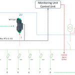
Grafik EN

Comprehensive cyber protection at field level

Cyber security, especially in critical infrastructure, is fundamental. Currently, it is reported that everywhere, not only in this specific area, attacks are increasing and doing their destructive work faster (e.g. Ransomware Lockbit 3.0, etc.). And that’s why any unprotected access (e.g. LAN ports, USB ports, SD ports, etc.) is also a potential risk. So do the connectivity variants of a measuring device. Be it via IT or even via the HMI. Imagine the many measurement data on the low voltage level, are manipulated. Intentionally or unintentionally. The result is pure chaos.

To counteract this, specific protection mechanisms have been implemented directly in the measuring instruments. The protection mechanisms are currently mapped via the secure protocol according to IEC61850, the HTTPS, an audit log (logbook of all manipulations), data loggers, access authorizations (RBAC) at various levels, client whitelist and the data transfer to a syslog server. In addition, the possibility of wireless communication via VPN gateway can be considered (attention: data volume/time unit).

Just screwed to the wall

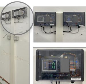
The LINAX PQ5000CL system can traditionally be mounted in the control cabinet on a DIN rail. Often, however, there is no more space in the existing systems and the effort of setting up a new control cabinet is out of proportion. So why not simply screw the base unit to the wall. Exactly for this case, the base unit was installed in a dust-protected IP23 housing and completely wired, including the necessary power supply of the Current Link modules. Mount, connect, done.

ewz bildergallerie

Fastest roll-out

The Current Link System not only takes into account the extremely high measurement and data performance, but also the uncomplicated hardware installation and software integration. The complete current measurement technology can be installed virtually during operation of the system. The non-invasive Current Link Modules with Rogowski technology on the measurement loops ensure a smooth, yet safe installation. Due to the coaxial ring bus cable, no additional and costly installation work is required. Not least because the Current Link modules are also supplied with the necessary operating voltage via the ring bus cable. If you also opt for the integrated variant in the IP23 housing, there is even no need for additional wiring in a control cabinet. And since the basic device already functions as a data concentrator, complex measured value integrations in the IT environment are reduced many times over.

Bild EN CL

Related Posts

Leave A Comment